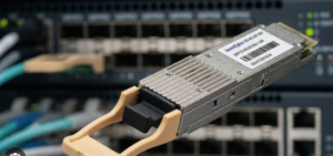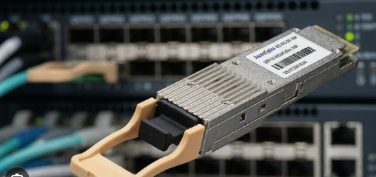
Ask any data center engineer what keeps them up at night, and chances are power budgets and thermal management are near the top of the list. The QSFP28 form factor has become the backbone of 100G Ethernet deployments, but its power consumption characteristics are often underestimated—sometimes with costly consequences.
Consider this scenario: a team sizes a rack PDU based on switch base loads alone, assuming plenty of headroom. They populate 64 ports with QSFP28 LR4 modules drawing roughly 4.5W each, and suddenly the optics alone are pulling nearly 300W per switch. Multiply that across multiple switches, and the math stops working. The breaker trips. The rack goes dark. Production stops.
This guide cuts through the speculation and gives you the per-module wattage data, the switch-level arithmetic, and the thermal framework you need to plan QSFP28 deployments that stay stable—not just on paper, but under real load.
Understanding What Drives QSFP28 Power Consumption
Not all 100G QSFP28 modules are created equal when it comes to power draw. The difference between a short-reach multimode module and a long-haul coherent module can be a factor of four or more. The primary drivers of power consumption fall into three categories: optical complexity, transmission distance, and signal processing requirements.
Short-reach multimode designs use VCSEL arrays and PIN photodetectors—relatively simple and power-efficient components. As you move to single-mode optics, you introduce DFB or EML lasers, wavelength-division multiplexing, and more sensitive receivers. Each step up in reach adds optical components that consume additional power. The real power jump happens when you introduce digital signal processors (DSPs). Coherent modules like ZR4 include DSPs that can consume nearly as much power as the rest of the optical engine combined.
Manufacturing variations also matter. Two modules with the same specification from different vendors can have different power profiles. Some manufacturers achieve sub-2W dissipation for SR4 designs, while others run closer to 3.5W. Always verify the specific power ratings for the exact SKU you plan to deploy rather than relying on generic averages.
Power Consumption by Module Type: A Reference Guide
Here is a practical breakdown of what to expect from common QSFP28 module types. These figures represent typical values across major vendors—always check your specific module datasheet for exact specifications.
SR4 (Multimode, up to 100m): 3.0–3.5W typical. These VCSEL-based modules are the most power-efficient option for intra-rack and spine-leaf links within the data center. The QSFP-100G-SR4-S is a widely deployed example in this category, delivering 100GBASE-SR4 connectivity over OM4 multimode fiber up to 100 meters with a typical power draw around 3.5W. It uses four parallel optical lanes operating at 850nm with an MPO-12 connector. For high-density deployments where every watt counts, SR4 modules are the clear choice.
CWDM4 and PSM4 (Single-mode, 2km): 3.5–4.0W typical. CWDM4 adds wavelength multiplexing across four lanes, while PSM4 uses parallel single-mode lanes. Both sit in a middle power tier between SR4 and LR4.
LR4 (Single-mode, 10km): 4.0–5.0W typical. This is the workhorse for campus interconnects and metro links. A fully loaded 48-port switch with LR4 modules adds roughly 216W from optics alone at a conservative 4.5W per module.
ER4 and ZR4 (40km–80km+): 4.5W to over 15W. Extended-reach modules require amplification, dispersion compensation, and in the case of ZR4, full coherent DSP engines. These are power-intensive components that demand serious thermal planning.
From Module to Rack: The System-Level Power Math
A single QSFP28 module drawing 3.5W doesn’t sound like much. But data centers don’t deploy single modules—they deploy switches filled with them, and racks filled with switches.
Here is the math that matters. A 64-port 100G switch fully populated with SR4 modules at 3.5W each consumes 224W from optics alone. The same switch with LR4 modules at 4.5W each consumes 288W. That is before you account for the switch ASIC, which itself draws significantly more power processing 100G traffic than it would at 40G because it must handle 2.5 times the bandwidth.
Now scale to the rack. A typical rack with four 64-port switches and LR4 optics pulls over 1,100W just from the optical modules. Add switch base loads, and you are approaching 3kW before factoring in power supply inefficiencies, fan ramp-up during temperature excursions, or future expansion.
The 80% rule exists for a reason. Never plan a PDU to its rated maximum. Transient loads, inrush current, and the reality that modules often draw more power at temperature extremes all demand headroom. If your calculated load hits 80% of PDU capacity, you are already in the danger zone.
Thermal Design: Keeping 100G QSFP28 Modules Within Spec
Power consumption is only half the story. The heat that comes with those watts must go somewhere, and QSFP28 modules have strict operating temperature limits.
The standard commercial operating case temperature range for QSFP28 modules is 0°C to 70°C. Some industrial-grade variants extend to -40°C to 85°C, but the vast majority of data center deployments use commercial-temperature parts. Exceeding 70°C case temperature can cause laser performance degradation, increased bit error rates, and eventual module failure.
Thermal management starts with airflow. Front-to-rear or rear-to-front airflow must match your switch and rack design. Passive DAC cables generally allow better airflow than optical modules because they lack the bulky optical engines, but they also have distance limitations. For optical modules, the key thermal variables are:
- Ambient inlet temperature: Keep it as low as practical. Every degree of inlet temperature rise pushes module case temperatures closer to the 70°C limit.
- Airflow volume and velocity: Dense port populations restrict airflow. A 64-port switch with cables in every port has significantly different airflow characteristics than a partially populated unit.
- Module spacing: Adjacent modules radiate heat to each other. The SFF-8679 specification addresses thermal characteristics of pluggable modules and provides guidelines for host system designers.
Practical thermal planning means simulating or testing your worst-case scenario: fully populated switch, maximum ambient temperature, worst-case traffic pattern, and failed fan scenario. If your modules stay below 70°C case temperature under those conditions, you have a robust design.
Avoiding Common Pitfalls in QSFP28 Power and Thermal Planning
The most expensive mistakes in QSFP28 deployments are the ones that could have been caught with better planning. Here are the traps to avoid:
Skipping the optics in the power budget. This is the number one error. Switch base power figures on datasheets rarely include optics. Add them explicitly—per port, per module type, at the maximum rated power, not the typical.
Assuming all modules are the same. A 100GBASE-SR4 QSFP28 module and a 100G LR4 module look identical from the outside but have very different power and thermal profiles. The 100G SR4 class is your lowest-power option for short links, while LR4 and beyond demand significantly more from your power and cooling infrastructure. The SR4 QSFP28 form factor delivers the same 100G throughput as its long-reach cousins but at roughly two-thirds the power draw.
Ignoring temperature derating. Module power consumption often increases at temperature extremes. A module rated at 3.5W at 25°C may draw 4.0W or more at 70°C case temperature. Plan your power budget using maximum power values, not typical.
Overlooking cable management. Dense cabling restricts airflow. MPO cables with tight bend radii can block the front panel and reduce the cooling air reaching the modules. Use proper cable management hardware and maintain recommended bend radii.
Forgetting about future expansion. If you populate 75% of ports today, design for 100% tomorrow. The incremental cost of upsizing a PDU or adding cooling capacity during initial deployment is far lower than a retrofit.
The 100G QSFP28 ecosystem offers tremendous density and performance, but that density comes with a thermal price. Plan for it from day one, and your deployment stays online through summer heat, traffic spikes, and everything in between. Skip the math, and you are gambling with production stability.
The PDU tripped at 11:47 AM on a Tuesday. Don’t let it be yours.